East Sussex Finescale
Lighting in your Track
Room
LED fluorescent tube replacement
and how the
re-wiring circuit works!
Certainly amongst the East Sussex Finescale group most
of us use fluorescent strip lighting in our trackrooms. Whilst fluorescent
tubes are likely to be around for many years to come LED tubes are now becoming
widely available. In this respect many of our group are looking to utilise this
new technology.
Essentially it appears there are two basic types of fluorescent light fittings:
1.
‘Old
style’ fluorescent light using starters.
2.
‘Modern
style’ fluorescent light using electronic ballasts.
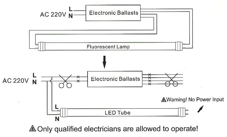
Fluorescent lamps using electronic ballasts needing
internal wiring modifications to accept LED tubes.
Moving
to LED Technology
Firstly, any mains electrical wiring should be
undertaken and signed-off by a qualified electrician; this page is not a wiring
instruction – merely an explanation as to why a wiring circuit is designed the
way it is. If you need instructions for electrical wiring then please consult a
qualified electrician and their accredited supplier.
The track room mainly uses 4’ T8 high-frequency
‘daylight’ fluorescent tubes and fittings; half of which are located above and
to the rear of the railway baseboards. Whilst tube-changing is straightforward,
if one of the high-frequency electronic ballasts failed it would be a struggle
to reach and replace.
With the advent of LED tubes, the decision was
taken to replace those fluorescent tubes located above baseboards with LED
types, this negating the future need to replace the electronic ballasts if ever
they failed.
A trial was undertaken with replacement of a
single tube. The result was far more impressive than expected, particularly in
terms of the much-improved quality of light from the LED tube. Accordingly, the
decision was made to replace all the fluorescent tubes (twenty-six in all).
Whilst the capital outlay is significant the
overall power consumption of the track-room’s lighting will also be halved from
900 watts to 450 watts.
ESF
debate
However, the rewiring for the light fittings (fluorescent
to LED) was slightly puzzling as there appears to be different wiring diagrams
promoted. Some of these diagrams meant the LED tube could only be fitted in one
direction; a dead short might be created if it wasn’t – as a qualified safety
professional (including industrial electrical engineering) this did not sit
comfortably.
Seeking to understand, this led to much debate
within East Sussex Finescale and an interesting
exchange of views. However, ultimately with a qualified electrician on-site (and
explanations found) others might be interested in the ‘why’ behind the circuit
used to re-wire the fluorescent light fittings in the track-room.
‘Old
style’ fluorescent light
(using starters)
The T8 replacement LED tubes each come with a
replacement unit for the starter. You simply replace the lamp’s starter and
tube and that should be that. Your lamp is now an LED fitment.
Accordingly, conversion to LED tubes should be
simple and straightforward without any wiring changes required in the light
fitting.
‘Modern
style’ fluorescent light
(using high-frequency electronic ballasts)
These need to be rewired and the high-frequency
electronic ballasts removed from circuit (if not from the light fitting). In
the track room it was simpler to have these taken out of circuit (disconnected)
and just leave them in the light fitting. The rewiring needed a new terminal
block fitted and a new 24” length of single core wire. As stated previously, a
qualified electrician will do this for you.
However, the circuit diagram for the LED tube
intrigued, leading towards wanting to understand exactly how it worked; particularly
as three of the LED tube’s pins appeared to be wired into the same circuit. In
reality it is slightly cleverer than that.
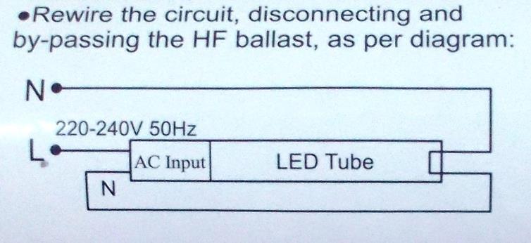
Manufacturer’s wiring both-ends
fed diagram
The Live feed enters the left-hand fitting (which
holds the tube’s left-hand end). In the diagram above this enters the LED
tube’s Input unit (as shewn above). However, there is a ‘link-wire’ that
carries the Neutral along the length of the LED tube into the right-hand
fitting (which holds the LED tube’s right-hand end).
The Neutral feed enters the right-hand fitting
which holds the LED tube’s right-hand side end. At the ‘non-input’ end of the
LED tube (as shewn above) the LED tube’s two pins are (internally) directly
connected together thus ensuring the Neutral is connected through to the LED
tube’s Input unit.
The LED tube will illuminate!
So why is
this circuit needed?
This circuit enables the LED tube to be
reversed; that is inserted with the Input end on the right-hand side (the other
way around to the diagram above).
As shewn above, the Live feed enters the
left-hand fitting (which holds the tube’s left-hand end). However, with the LED
tube reversed the Live feed simply connects across to the second pin and the ‘link-wire’
now carries the Live (not Neutral) along the length of the LED tube into
the right-hand fitting (which holds the LED tube on the right-hand side) and into
the LED tube’s Input unit.
The Neutral feed enters the right-hand fitting (which
holds the LED tube’s right-hand end). This means the Neutral is now connected directly
to the LED tube’s Input unit.
The LED tube will illuminate!
In summation
i.
the
LED tubes use bridge-rectifiers from the AC mains input;
ii.
the
‘link-wire’ will be Neutral if the LED tube is inserted with the Input-end to
the left;
iii.
the
‘link-wire’ will be Live if the LED tube is inserted with the Input-end to the
right;
iv.
the
LED tube can be inserted either way round!
So why
not just connect the Live and Neutral to one fitting-end?
If both the Live and neutral were connected to
the left-hand fitting (which holds the tube’s left-hand end) the tube would
work provided the LED tube has been inserted with its Input at that end. Some manufacturer’s
diagrams portray this arrangement.
Manufacturer’s wiring single-end
fed diagram
However, if the tube is fitted the ‘wrong-way
round’ then a dead-short will be created. The is because the other two pins of
the LED tube are directly connected together.
Placing an LED tube into a light fitting thus
wired would mean the installer will need to know:
a)
Which
end of the light fitting is ‘live’ &
b)
At
which end of the LED tube is its Input (some are clearly marked).
Ultimately
consult a qualified electrician!
Fluorescent light fittings using high-frequency
electronic ballasts should be rewired by a qualified electrician. However, at
least now the modeller can understand the reasons for this interesting piece of
circuitry.
Return to East Sussex Finescale’s home page
Link to BloodandCustard modelling
pages
ALL
PHOTOGRAPHS ARE COPYRIGHT